It is closely related to Permanent-magnet wheel of earlier design – CLICK HERE, but it is a more specific mechanism. Both designs attempt to produce continuous rotation by changing the magnetic forces around a wheel. The new description adds a piston-like mechanism that moves two magnets back and forth while a stationary, half-round ferromagnetic steel plate provides the attraction force.
The central claim is that pushing two like poles together reduces the attraction to steel, and separating them restores the attraction. The proposed engine uses this change to create a difference in forward and backward forces.
There is a useful engineering idea to investigate here: the magnetic attraction to steel can change when the magnet arrangement changes. However, that observation alone does not prove that the complete engine can produce continuous net power.
1. How the two designs compare

Multiple magnet assemblies arranged around the wheel.
The geometry is intended to balance compression and release.
Magnetic forces are supposed to create forward rotation.
The design claims a net force after subtracting the backward pull.

A rotating crankshaft has an offset of ½ inch.
Two magnets move back and forth over a 1-inch stroke.
Like poles face each other to create repulsion.
A stationary semicircular steel plate is attracted to the rotating magnet assembly.
The mechanism aims to reduce magnetic attraction at one point and restore it at another.
The main difference is how the magnetic arrangement changes during rotation. Your first design describes compression and decompression around the wheel; the second explicitly uses a crank-driven reciprocating mechanism to change the spacing of the magnets.
The second design is therefore a more detailed mechanical implementation of a related concept, not a completely different principle.
2. The claimed magnetic effect: is it physically possible?
The description says that two magnets with their south poles facing each other repel, and that bringing them together reduces the attraction of the assembly to the steel plate.
The first part is established physics: like poles repel, and magnets attract ferromagnetic materials such as iron.
The three configurations to test

Measure the attraction to the steel plate as a baseline.

Measure the steel attraction while the magnets are close together. Also measure the force required to hold them there.

Repeat at different separations, including the proposed 1-inch stroke, and measure both forces again.
A useful scientific distinction: the magnets’ own magnetization need not change significantly for the force on the steel to change. The external field distribution and the interaction with the steel can change even when the permanent magnets themselves remain magnetized.
3. How the piston and crankshaft change the design
The new design uses a crankshaft offset by ½ inch to move the two magnets through a 1-inch total stroke.

This creates an important mechanical relationship:
As the crank moves the magnets together, it must overcome their repulsion.
As the magnets move apart, the repulsive force may help drive the crank.
The steel plate can exert different forces at different crank positions.
Those forces create torque on the rotating assembly, but the total torque must include the forces required to move the pistons.
The crankshaft is not an independent source of energy. It transmits energy between the rotating wheel and the reciprocating magnets. The question is whether the changing magnetic interaction produces a net positive work over a complete cycle after all those contributions are counted.
4. Does using a stationary steel plate solve the energy problem?
The description insists on using iron or ferrous metal instead of another permanent magnet. That is a meaningful design choice because steel responds differently from a permanent magnet, and it changes the magnetic circuit. It does not, by itself, eliminate the energy balance.
The steel plate can attract the magnets strongly at one position and less strongly at another. But the work required to change the magnetic configuration must be considered alongside the work the steel attraction delivers.
For a complete cycle, the key test is:
Measure the signed torque throughout one full revolution. If the system returns to its initial mechanical and magnetic configuration, with no external energy input, a repeatable positive net output would require careful independent verification.
A force reading of 900 gf at one position and 60 gf at another does not establish a net output of 840 gf, because the forces may act in different directions and over different distances.
5. Which design is better to build first?
| Consideration | Original magnet wheel | Piston magnetic engine |
|---|---|---|
| Mechanical complexity | Lower if magnets are fixed | Higher because pistons and crank are needed |
| Ability to vary magnet spacing | Limited unless additional mechanisms are added | Built into the design |
| Measuring compression and release | Possible | Easier to isolate and instrument |
| Important unknown | Net torque around the wheel | Net torque plus energy needed to move the pistons |
| My recommendation | Good for a simple initial force test | Better for investigating the specific piston concept |
My recommendation is to start with the three-magnet test rig described in the new design. Use one magnet facing the steel plate and two magnets in a guided, like-pole-facing arrangement. Measure the steel attraction and the piston force separately while varying the spacing.
That will establish whether the reported reduction in steel attraction is reproducible. The next step is to connect the mechanism to a crank and measure torque through 360 degrees.

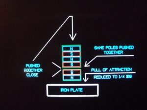
These images clarify the mechanism considerably. The second image shows the key arrangement you described: two magnets with like poles facing each other, positioned above an iron plate, with the aim of reducing the plate’s attraction while the magnets are pushed together.
1. What experimental photographs show
Image 1 — Physical test setup
The photograph shows a metal support, hanging rings and a magnet-testing arrangement. It appears to be intended to demonstrate changes in force as the magnet configuration changes. The photograph alone does not establish the measured force or how it was calibrated.

Image 2 — The proposed magnetic arrangement
The diagram depicts a stack of magnets with alternating north and south poles. The lower magnet assembly faces the iron plate, and like poles face each other at the interface between the two assemblies. The stated objective is to reduce the pull on the plate to approximately ¼ pound.
The physical arrangement is relevant to your magnetic-engine concept. However, the exact force change needs to be verified with a controlled test, because the field produced by the entire magnet stack—not just the two facing poles—determines the attraction to the iron.
2. The exact test I would perform next
Your diagram appears to show the upper stack ending in a south pole and the lower magnet beginning with a south pole. These like poles repel. The lower magnet’s other end faces the iron plate, creating the attraction you want to measure.
To verify the claim, use this procedure:
Baseline: Measure the attraction between the magnet assembly and the iron plate without the upper magnets pushing against the lower magnet.
Compression test: Bring the upper and lower magnet assemblies together with the south poles facing. Measure the force pulling the assembly toward the plate.
Separation test: Separate the magnets by a known distance, such as 25.4 mm (1 inch), and measure the plate attraction again.
Repeat: Perform each measurement several times, keeping the plate, magnet orientation, plate gap and measuring equipment consistent.
Measure the compression force separately: Record how much force is needed to push the magnets together and pull them apart.
The important distinction is that the force between the magnets and the force between the magnets and the iron plate are two different measurements. Both are needed to evaluate the proposed engine.
3. What the results would tell us
| Experimental result | What it would establish |
|---|---|
| Plate attraction decreases when the magnets are compressed | Supports the claimed magnetic-force effect for that arrangement |
| Plate attraction returns when the magnets separate | Confirms a reversible change in attraction |
| Forward force exceeds backward force at selected positions | Shows a force difference at those positions |
| Net torque remains positive throughout a complete cycle after accounting for resetting and losses | Would be evidence to investigate further; it still needs independent energy measurements |
Even if the first two results are confirmed, they do not by themselves establish continuous power production. The crankshaft must do work to compress the magnets, and that work must be included in the full-cycle energy balance.
My conclusion: Your photographs show a testable magnetic arrangement that is relevant to the proposed magnetic piston engine. The next step is to verify the force measurements accurately, then test the complete crankshaft mechanism under load. That is the most direct way to determine whether the concept can produce useful net mechanical output.